


Full feature list
DIgSILENT PowerFactory offers a range of load flow calculation methods, including a full AC Newton-Raphson technique (balanced and unbalanced) and a linear DC method. The enhanced non-decoupled Newton-Raphson solution technique with current or power mismatch iterations, typically yields round-off errors below 1 kVA for all buses. The implemented algorithms exhibit excellent stability and convergence. Several iteration levels guarantee convergence under all conditions, with optional automatic relaxation and modification of constraints. The DC load flow, solving for active power flows and voltage angles, is extremely fast and robust (linear system; no iterations required).
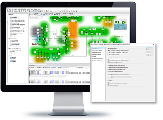
- Balanced and unbalanced load flow for coupled AC and DC grids
- Meshed DC supergrid load flow analysis
- State-of-the-art numerical solvers for fast and robust convergence from arbitrary starting-points
- Active/reactive power and voltage regulation options, such as SVC, shunt and tap controllers
- Station- and network control features, including Q(U)-, cosphi(P)-, Q(P)-, and droop characteristics
- Local- and remote control options
- Secondary and primary control, inertial response
- Distributed slack by load and generation, including interchange schedules
PowerFactory provides short-circuit calculations for single and multiple faults, together with a number of reporting options. As short-circuit calculations are needed for a variety of purposes, the short-circuit calculation in PowerFactory supports different representations and calculation methods based on a range of international standards, as well as the superposition method (also known as the Complete Method), which is based on a specific network operating point and provides the required algorithms and precision for determining the “true” or “operational” short-circuit currents without considering the simplifications or assumptions typically made in standard fault analysis.
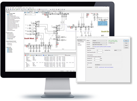
- Support of IEC 60909 (including 2016 edition), IEEE 141/ANSI C37, VDE 0102/0103, G74 and IEC 61363 norms and methods
- Calculation of short-circuit currents in DC grids according to IEC 61660 and ANSI/IEEE 946
- Complete superposition method, including dynamic voltage support of generators connected via power electronics
- Multiple fault analysis of any kind of fault incl. single-phase interruption, inter-circuit faults, fault sweep along lines, customisable short-circuit sweep diagrams etc.
Supplementing PowerFactory’s Load Flow Analysis is the Sensitivities / Distribution Factors tool. Based on a static voltage stability calculation, it enables the user to know not only the critical points in the network but how these critical points are affected by changes in system conditions. The range of sensitivity factors which can be calculated includes standard distribution factors such as PTDF and OTDF.
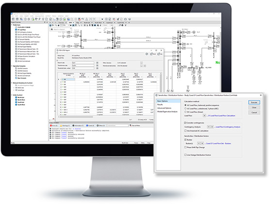
- Comprehensive range of voltage and branch flow sensitivity calculations
- Transformer and booster sensitivities (continuous and discrete)
- Standard distribution factors (PTDF, LODF, OTDF, PSDF and TCDF)
- Single and multiple sensitivities
- Consideration of contingencies*
- Flexible reporting options
The Load Flow analysis capabilities are enhanced by dedicated functionality for the assessment and planning of MV and LV distribution networks.
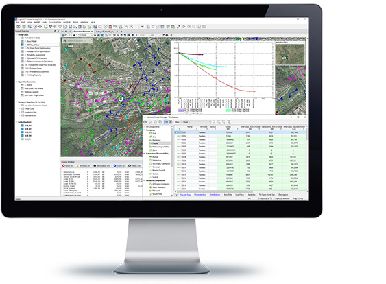
- Voltage profile plots for single and muliple feeders
- Feeder analysis tools incl. feeder load scaling for simple & meshed feeders
- Automated schematic visualisation of feeder topology
- Radial feeder tools incl. voltage and phase technology change tools
- Backbone calculation determining the main connections between meshed feeders
- LV network analysis functions
- Stochastic load modelling
A comprehensive suite of power equipment models and libraries is available in PowerFactory, to enable the modelling of all network elements, together with controllers and protection devices.
- Large and comprehensive Equipment Type Library, fully version-controlled with regular model updates
- Various synchronous and asynchronous motor/generator models (single- and three phase)
- Asynchronous machine parameter identification
- Doubly-fed induction machines
- Static generator for modelling wind- and PV-generators, fuel cells, micro-turbines, etc.
- PV system with integrated power calculation based on solar radiation
- External grids, AC and DC voltage and current sources
- Simple and complex load model, special MV and LV load models, including input based on yearly energy values and load profiles
- Network branches (OHL, cable, branches, line couplings, tower geometries, cable systems, busbar trunking systems, 2-winding transformer and auto transformer, 3-winding transformer and auto transformer, 4-winding transformer and autotransformer, booster transformer, step-voltage regulator, reactor, series ¬capacitor, common impedance, etc.)
- Overhead line and cable parameter calculation
- Controller objects such as station & secondary controller including various control methods, ¬transformer tap controller, virtual power plants, capability curves
- Static var compensation (SVC), thyristor controlled series compensation (TCSC, shunt/filter models, and harmonic filters (single-tuned, ¬double-tuned, high pass)
- Modelling of HVDC interconnections (rectifier/inverter, two-level VSC, half- and full-bridge MMC converter)
- Power electronic devices and discrete components (diode, thyristor, PVM converter, rectifier/inverter, DC valve, soft starter, etc.)
- DC/DC converter, inductive DC-coupling
- DC Battery, DC machine and DC load models
- Explicit modelling of neutral wiring
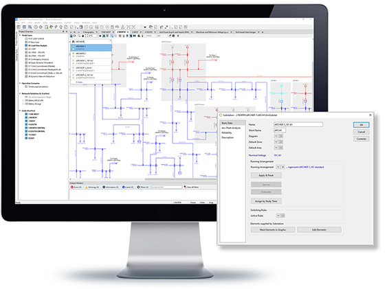
PowerFactory supports all network representations and phase technologies, i.e. any kind of radial or meshed 1-, 2-, 3- and 4-wire (combined) AC and DC network. Building a network is also facilitated through the provision of standard substation models.
- Support of any kind of meshed/radial 1-, 2-, 3- and 4-wire AC and DC networks with combined AC and DC modelling for all available analysis functions
- Single-phase, two-phase, bi-phase and three-phase technology with/without neutral
- Hierarchical data model including sites, substations, bays, primary and secondary equipment
- Detailed primary and secondary substation models (single/double busbars w/o tie breaker, 1-1/2 busbar, bypass busbar), extendable for user-specific busbar configurations including protection schemes
- Switches and substation equipment such as CB, fuse, disconnector, load break switch, grounding switch, NEC/NER, CT, VT, CVT, combined CT/VT, etc.
- Running arrangements and switching rules for substation automation
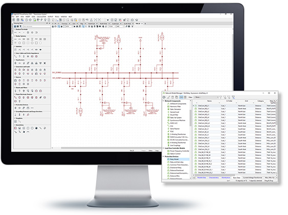
PowerFactory is used within a single-user or multi-user hierarchical, object-oriented database, containing all the data required for analysis, organised in libraries and PowerFactory projects. Flexible tools are offered for viewing, handling and sharing data, and for managing user accounts and projects, including options for archiving and database housekeeping.
Single- and Multi-User Edition
- User-friendly and powerful Data and Object Manager
- Network Model Manager with spreadsheets for convenient management of network equipment data and results
- Flexible grouping and filter functionality
- Grid Variations management with time-stamped grid Expansion Stages
- Highly flexible Study Case concept with definable Operation Scenarios, Variations, Grids and Triggers
- Project Overview window and Study Case Manager for simplified management of Study Case configuration
- Data (Model) Extension concept for user customisation with user-defined classes and attributes
- Flexible parameter characteristics
- Master- and Derived Projects with Merge Tools
- Project combination and project connection assistant (horizontal/vertical)
- Project versioning
- Database Undo and Rollback function
Team Edition
- Includes all Multi-User Edition features
- Multi-User database with team working functionality and support of simultaneous user sessions
- User accounting, data access and function access rights
- User authentication via PowerFactory user administration, including password policy settings, or via external authentication services, such as LDAP or Microsoft Active Directory
- Database housekeeping mechanisms
- Project archiving
- Offline Mode via locally cached database and possibility for synchronisation with multi-user database when connected to the network (requires Network Licence with Floating Licence)
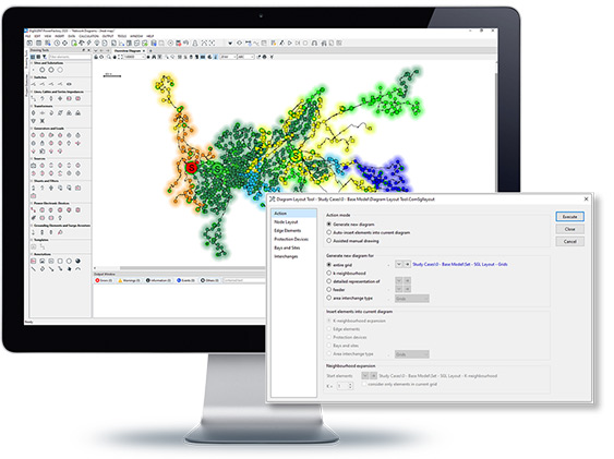
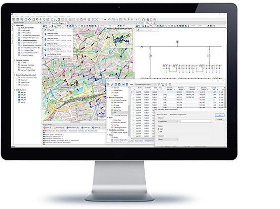
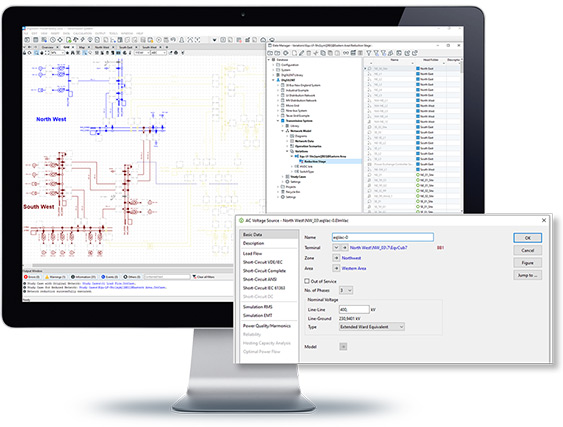
PowerFactory has a range of flexible tools to enable the user to visualise electrical networks, including geographic representations based on GPS coordinates. Features include easy navigation between graphics and data, diagram layers and many diagram colouring options. Customised graphics can be created but there is also a diagram layout tool for the automatic generation of network diagrams.
- Simplified single line diagrams for schematic and design views
- Detailed single line diagrams showing full switch & component model including primary and secondary equipment
- Graphical representations of sites, substations and bays
- Intelligent Overview Diagrams supporting node & branch views
- Geographic Diagrams (GPS-based) with background maps
- Background Maps representation automated via mapping server interface (e.g. Open Street Map, Google Maps*, Esri ArcGIS*)
- Automated generation of Area Interchange Diagrams
- Graphic search option for network elements in diagrams, including geographic search
- Flexible diagram layer concept with opacity settings for customisable layer combinations, including annotation layers for enriched visualisation options (network diagram, maps, images, texts, plots, etc.)
- Single line diagram handling across Variations and Expansion Stages
- Automated drawing of Site and Substation Diagrams
- Diagram Layout Tool for auto-drawing or assisted drawing of full or partial network, feeders, protection devices (CTs, VT, relays), branches, site and substation diagrams as well as auto-expansion of diagram
- User-definable symbols and composite graphics
- Global template libraries (e.g. for substation configurations, WTGs, PV systems)
- Numerous diagram colouring and result visualisation modes
- Flexible Heatmap background colouring scheme
- Navigation Pane facility
- View Bookmarks for quick navigation between zoom areas
- Diagram export and printing functionality with comprehensive print configuration options
- Tabbed windows with browser-like navigation
- Interactive split views for simultaneous working in multiple diagrams or plots
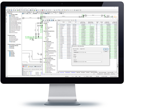
Results and other data can be presented to the user in a variety of ways, including inbuilt spreadsheet-style or text reports and configurable presentation of results on graphics or in tabular format. Interactive plots can also be easily generated and customised.
- Extremely rich set of calculation quantities
- Comprehensive text and interactive spreadsheet reports
- Tabular result views via configurable Flexible Data pages
- Export of results to standard data formats
- Flexible reporting and result visualisation in network diagrams
- Interactive output window with flexible filter functionality
- Numerous interactive plots for result visualisation (differential and time-over current protection, harmonics, stability and transients, eigenvalue analysis, etc.)
- Easy-to-use plot navigation (e.g. scaling, zooming, moving/sliding, stretching/compressing, etc.)
- Intelligent Plots with statistics functionality
- Digital Signal plot and Fault Recorder view
- Powerful results comparison mode
- Running arrangements and switching rules for substation automation
The PowerFactory base package allows for the import and conversion of network model data from a number of other modelling applications. In addition, bi-direction data exchange is possible using a DGS interface tool which supports a range of data formats.
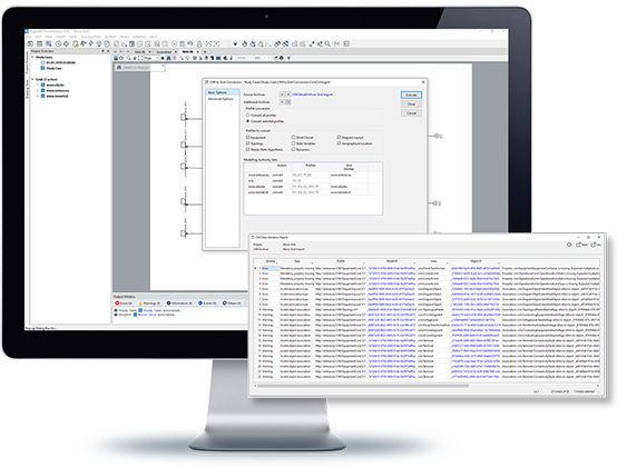
- Support of various data conversion and interfacing options for bi-directional data exchange
- DGS interface: Bi-directional, flexible DIgSILENT data exchange format (ASCII, XML, CSV, ODBC) supporting GIS and SCADA interfacing
- Data import converter:
- PSS/E, PSS/U (Siemens/PTI)
- Sincal (Siemens)
- UCTE (ENTSO-E)
- CIM data exchange tools* (ENTSO-E Profiles 2009, CGMES 2.4.15 certified) including CIM model editor and validator
- Neplan
- Integral 7 (FGH)
- Elektra
- ISU (SAP)
- Reticmaster (Inspired Interfaces)
- PRAO*
- Data export converter:
- CIM1 (ENTSO-E Profiles: 2009, CGMES 2.4.15 certified)
- UCTE1 (ENTSO-E)
- PSS/E1 (Siemens/PTI)
- Integral 7* (FGH)
* Not part of the base package; this function has to be requested separately.
PowerFactory is easy to use and fully Windows compatible and can be integrated with other packages to meet the requirements of all power system analysis applications.
- Comprehensive examples including linked demo videos on the DIgSILENT YouTube channel
- Interactive introductory tutorial
- Complete and well-structured User Manual (1200+ pages)
- Detailed Technical References for all Power Equipment models
- User-friendly GUI with new modern appearance, available in multiple languages
- Output window including icons, colours, tabs and filters for categorisation and visualisation
- Integrated script editor
- User profiles with customisable toolbars, dialogs and context menus
- Functional integration for all power system applications incl. T&D, industry, renewables, smart grids, etc.
- Various interfaces for communication and data exchange with third-party systems
- Fully compatible with MS Windows 32- and 64-bit versions
- Compliance with GDPR (General Data Protection Regulation)
The Contingency Analysis tool in DIgSILENT PowerFactory has been designed to offer a high degree of flexibility in configuration, calculation methods and reporting options. Single- and multiple- time-phase contingency analyses are available, both of which offer automatic or user-defined contingency creation based on events, and the consideration of controller time constants and thermal (short-term) ratings.
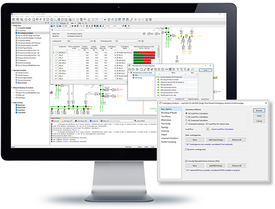
- AC, DC and AC linearised analysis methods, including regional assessment
- Fast contingency screening with recalculation of critical cases using AC method
- Single and multiple time phase consideration
- Dynamic contingencies option for creating fault cases “on the fly”
- Remedial Action Schemes for flexible and dynamic analysis of post-fault actions
- Substation automation via switching schemes
- Automatic time sweep contingency analysis of a 24 hour time period incl. parallelisation
- Generator effectiveness and quad booster effectiveness
- Comprehensive spreadsheet reporting features incl. graphical visualisation of critical cases
- Tracing of individual contingency cases
- Contingency comparison mode
- Support of parallelised Contingency Analysis for multiprocessor hardware
- Reloading of results
Power Factory offers Quasi Dynamic Simulation for the execution of medium to long term simulations. Multiple load flow calculations are carried out with user-defined time step sizes. The tool is particularly suitable for planning studies in which long term load and generation profiles are defined, and network development is modelled using variations and expansion stages.
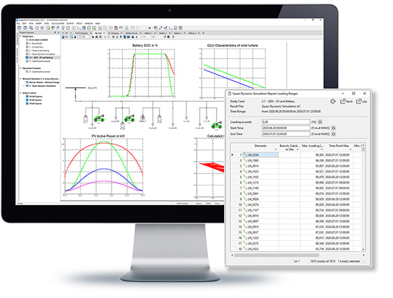
- Medium- to long-term simulations based on steady-state analysis
- Time and Time-Profile characteristics for simplified modelling of (recurrent) time series
- Consideration of planned outages, network Variations & Expansion Stages
- Flexible definition of simulation time range with arbtirary resolutions
- Simulation plots and tabular reports including statistical analysis
- QDSL-language for user-definable models (load flow and quasi-dynamic equations)
- QDSL model encryption funcionality*
- Support of parallelised simulation on multiprocessor hardware
- Reloading of results
The Network Reduction Tool enables the analysis of networks where the effect of adjacent networks needs to be considered but are not required to be modelled in detail. Adjacent networks are reduced according to a user-specified boundary, with the tool creating the required equivalent elements for subsequent load flow and short circuit calculations.
- Flexible definition of boundaries with Boundary Definition Tool
- Calculation of (AC or DC) load flow and short-circuit equivalent
- Network Reduction for Dynamic Equivalent, to support balanced RMS simulations*
- Support of load, Ward, extended Ward and REI-DIMO equivalents
- Numerous options for aggregation of non-linear elements
- Capturing of reduction via Variation for convenient toggling between original and equivalent grid
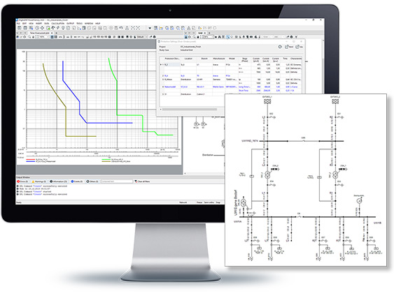
A comprehensive relay library based on manufacturer-specific protection devices is available and can be used in steady-state and for dynamic simulation. The protection device models are highly detailed and completely aligned with StationWare, allowing settings exchange with real protection devices. A range of protection concepts is supported, including time-overcurrent, distance, differential, directional, over-voltage and under-voltage, over-frequency and under-frequency, out of step protection and power swing blocking. Various graphical representation of protection device characteristics are available such as Overcurrent-time diagram with drag and drop functionality, R-X and P-Q diagrams, and diagrams for differential protection. Validation of selected settings can be done graphically via Time distance diagrams or with Overcurrent-time diagrams, or automatically via protection audit tools. Selected settings can be reported in tables and exported for further investigation.
Protection Functions are offered in two packages:
- Comprehensive relay library with relay models suitable for steady-state, RMS and EMT calculations
- Synchronisation with DIgSILENT StationWare
- Highly-detailed spreadsheet reports for protection settings (overcurrent, distance, voltage, frequency protection)
- Graphical visualisation and editing of fuses, relays, CTs and VTs including auto layout functionality
- Protection Audit
- Validation tool for protection settings and configurations
- User-configurable fault types assessment
- Automatic determination of protection topology
- Automatic short-circuit calculation
- Multiple predefined reports with auto-identification of critical protection settings (device coordination, device tripping times, fault clearing times)
- Short-Circuit Trace functionality for steady-state simulation of fault clearance and relay responses
- Overcurrent-time diagram with drag & drop functionality including auto-generated graphical legend
- Cable and transformer damage curves
- Motor starting curves
- Automatic display of measured currents
- Steady-state response checks
- Steady-state short-circuit simulation with tracing of individual steps
- Steady-state tripping times for transient or sub-transient current/voltage values
- Transient response checks (requires Stability Analysis functions (RMS) or Electromagnetic Transients functions (EMT))
- Protection Graphic Assistant
- Customisable short-circuit sweep diagrams including visualisation of protection settings
- Protection model features
- Fuses and low-voltage circuit breakers
- Positive-, negative-, zero-sequence inverse and definite time characteristics
- Thermal overload characteristics
- Directional elements supporting cross-, self- and memory polarising, Wattmetric method
- Differential unit with harmonic blocking for multiple harmonic orders
- Generic and detailed manufacturer-specific recloser units
- Signal transmission between relays, inter-tripping, interblocking schemes
- Detailed CT, VT, combined CT/VT , and CVT models including ¬ saturation
- Over-, under-voltage inverse and definite time characteristics
- Programmable logic unit
- Over-, under-frequency and df/dt inverse and definite time characteristics*
- Includes full “Time-Overcurrent Protection” module
- P-Q diagrams and R-X diagrams with support of the display of measured impedance trace
- Time-distance diagrams, with metric or calculated display of zone reach in forward and reverse direction
- Protection Graphic Assistant
- Reach of protection zones colourings in diagrams
- Protection Coordination Assistant
- Automatic calculation of protection settings
- Support of various coordination methods and setting rules, including user-defined rules
- Protection model features
- Generic and detailed manufacturer-specific Mho, polygonal distance zones and distance starting units
- Out of step detection and power swing blocking unit*
*Requires Stability Analysis Functions (RMS) licence.
Distance Protection
The Arc-Flash Analysis tool supports various international recognised standards and recommendations for Arc-Flash Hazard calculations. All calculation results can be represented graphically or in tables and Arc-Flash labels can be generated. Different ways of specifying the fault clearing time are offered; if the Protection Functions licence is available, the Arc-Flash Analysis can be configured to take into account protection devices and their fault clearing times.
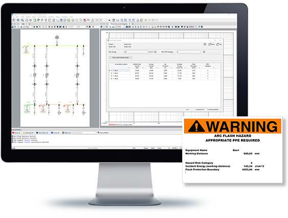
- Arc-Flash calculation in accordance with IEEE 1584-2002 and -2018, NFPA 70E-2012 and BGI/GUV-I 5188
- Incident Energy, Flash-Protection Boundary and PPE Category on the single line diagram
- Automated preparation of Arc-Flash labels via MS Excel/Word
- Automatic protection-based fault clearing time determination*
- Calculation of arcing-current energy
The PowerFactory Cable Analysis tool contains two packages: Cable Sizing and Cable Ampacity Calculation. The Cable Sizing package can be used either to verify the suitability of the assigned line types or to obtain recommendations for new line types according to a selected International Standard or according to user-defined voltage, thermal, and short-circuit constraints. The Cable Ampacity Calculation assists in the determination of the maximum allowed current of a cable by taking different factors into account such as conductor temperature, the local environment and other cables nearby.
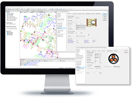
- Automatic cable sizing based on IEC 60364-5-52, NF C15-100, NF C13-200, and BS 7671, etc.
- Cable reinforcement optimisation
- Verification of global and/or individual thermal and short-circuit constraints
- Verification of user-defined voltage drops per terminal and/or feeders
- Balanced (positive sequence) or unbalanced calculation with support of all phase technologies (1-, 2- and 3-phase systems, w/o neutral conductor)
- System phase technology and cable types consistency checks in the feeder
- Various verification reports and automatic modification of cable types in the existing network via network Variations
Cable Ampacity Calculation
- Cable Ampacity calculation based on IEC 60287 or Neher-McGrath method
- Evaluation of maximum allowable current for cables based on cable material, laying arrangement and environmental data including presence of external heat sources
- Convenient cable layout modelling capabilities, supporting all laying arrangements of single and multi-core cables
- Rich reports and automatic modification of cable derating factors in the existingnetwork via network Variations
Cable Sizing
With the Harmonic Load Flow Calculation and the Frequency Sweep Calculation, the user is able to analyse the modelled network in the frequency domain. The frequency-dependent network impedance offers valuable clues about possible resonances in the network and the effectiveness of countermeasures. The harmonic load flow combines the network impedance with harmonic sources, resulting in the level of the harmonic distortion for each location in the network.
Harmonic Load Flow
- Harmonic voltage and current indices (IEC 61000-3-6, BDEW 2008)
- Balanced (positive sequence) and unbalanced (multiphase) model
- Unbalanced harmonic sources
- Non-characteristic and inter-harmonics
- Multiple harmonic injections: current and voltage sources, thyristor rectifiers, PWM-converters, SVS, non-linear loads, Norton-equivalents
- Background distortion frequency-dependent R and L values
- Various harmonic distortion indices such as THD, HD, HF, THF, TAD, TIFmx, total RMS currents and voltages, loadings and losses (defined according to IEEE and DIN/IEC standards)
- Harmonic distortion plot with pre-defined distortion limits according to international standards
- Waveform plots
- Calculation of K-Factors and Loss Factors for 2-winding transformers (UL1562, EN 50464-3 (replaces BS7821), EN 50541-2, IEEE C.57.110-1998)
Flicker Analysis
- Flicker Assessment (IEC 61400-21):
- Short- and long-term flicker disturbance factor for continuous and switching operations
- Relative voltage changes
- Flickermeter (IEC 61000-4-15):
- EMT or RMS signals
- Support of multiple file formats as COMTRADE,CSV, user-defined, etc.
Frequency Sweep
- Automatic step size adaption or constant step size
- Balanced (positive sequence) and unbalanced network model
- Self and mutual impedances/admittances (phase and sequence components)
- Frequency-dependent R and L values and line/cable models
- Spectral density of voltage amplitude/angle
Filter Analysis
- Various filter models
- Design and layout parameters
- Filter sizing and verification reports
- Ripple control analysis
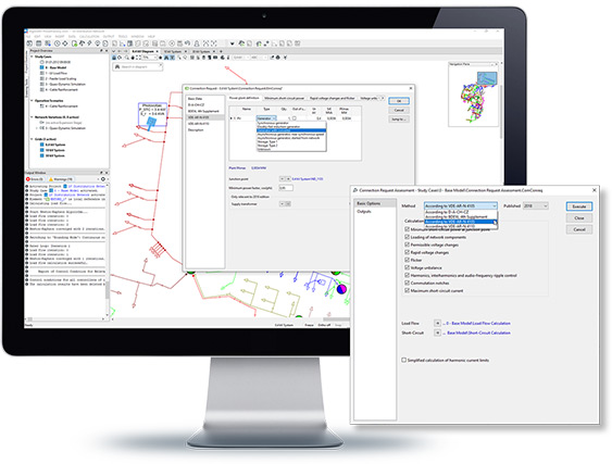
The assessment of connection requests is simplified with this dedicated tool, which supports the D-A-CH-CZ, BDEW and VDE-AR-N 4105 guidelines. After creating and configuring the Connection Request element based on the given data, the assessment can be performed like any other calculation. The output report shows dedicated results for each of the aspects to be assessed, such as voltage changes, flicker and harmonics.
- Supported standards and guidelines:
- D-A-CH-CZ guidelines
- BDEW 2008, 4th supplement
- VDE-AR-N 4105 guidelines (2011 and 2018)
- VDE-AR-N 4110 guidelines (2011 and 2018)
- Assessment of:
- Voltage changes and flicker
- Voltage unbalance
- Loadings and short-circuit currents
- Harmonics, interharmonics, audio-frequency ripple control
- Commutation notches
- Interharmonic voltages
- HV resonances
- Ripple control analysis
This suite of tools aimed at transmission network operators and planners includes options for analysing the voltage stability and power transfer capabilities of the network. With this module, the Outage Planning module is also provided, offering the capability for modelling planned outages and associated system reconfigurations.
PV curves calculation
- Voltage stability assessment by determination of critical point of voltage instability
- Support contingency analysis, i.e. detection of “limiting contingency”*
QV curves calculation
- Voltage stability limit assessment by evaluating the bus voltage change w.r.t. variation of injected reactive power
- Evaluating of stable operating points for various system loading scenarios, including contingencies*
- Determination of reactive power compensation by superposition of capacitor characteristics in QV plots
Power Transfer Distribution Factors
- Analysis of the impact of a power exchange between two regions
- Various load and generation scaling options
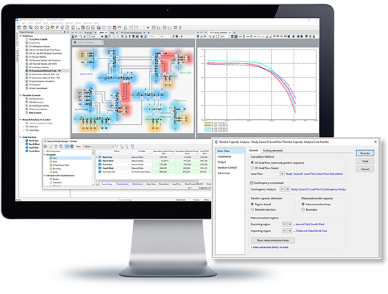
Transfer Capacity Analysis
- Determination of maximum power transfer capacity between two regions
- Various load and generation scaling options for exporting and importing region
- Thermal, voltage and contingency* constraints options
Outage Planning
The Outage Planning module is part of the Transmission Network Tools. Details see in main chapter Outage Planning.The Distribution Network Tools functions can be used to analyse and improve the key aspects of a distribution network. The range of tools begins with the determination of the optimal tie open point according to the minimisation of losses or reliability indices, whilst observing network constraints. It continues with the optimisation of the voltage profile, with the objective to be prepared for a growing number of distributed energy resources or a growing number of loads within the LV network through estimation of the optimal tap position of the distribution transformers. For unbalanced network conditions, the phase balance optimisation helps to find an optimal balance for the load and generation units between the three phases. The package also includes a tool for optimising capacitor placement and a hosting capacity tool for evaluating the maximum distributed energy resources and/or spare load capacity of the network.
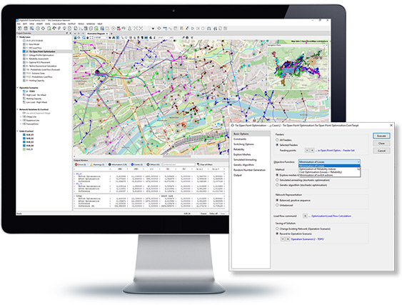
Tie Open Point Optimisation
- Optimisation of tie open point positions subject to loss minimisation, ¬improvement of system reliability, or minimisation of switching actions
- Support of balanced/unbalanced systems
- Branch and boundary flow limits, absolute voltage, and voltage drop/rise constraints
- Enhanced reporting features and graphical visualisation, including ¬automatic identification of tie open points
- Various methodologies, such as mesh exploration heuristic, ¬genetic algorithms, and simulated annealing
QV curves calculation
- Voltage stability limit assessment by evaluating the bus voltage change w.r.t. variation of injected reactive power
- Evaluating of stable operating points for various system loading scenarios, including contingencies*
- Determination of reactive power compensation by superposition of capacitor characteristics in QV plots
Voltage Profile Optimisation
- Verification and optimisation mode
- Voltage profile optimisation for bi-directional power flows in systems with a high level of distributed generation
- Determination of optimal distribution transformer tap positions for production and consumption cases (simultaneous or independent)
- Combined consideration of MV and LV feeder voltage profiles with enhanced plotting features
Phase Balance Optimisation
- Automatic reconnection of loads, generators, and/or branch elements in order to achieve minimal power unbalance
- Minimisation of unbalance at feeding point or average unbalance in feeder
- Support of heuristic method as well as simulated annealing approach
- High flexibility to also allow for partial reconfiguration
- Capturing of results via Variations for convenient toggling of original and optimised phase connections
- Various methodologies, such as standard heuristics, genetic algorithms, and simulated annealing
Optimal Capacitor Placement
- Determination of optimal locations, types, phase technology and sizes of capacitors
- Economic assessment considering costs of losses against installation costs under predefined voltage constraints
- Support of load variation via characteristics
Hosting Capacity Analysis
- Evaluation of the maximum distributed energy resources (DER) and/or spare load capacity of a network
- Consideration of thermal, voltage, protection* and power quality limits**
- Graphical visualisation of maximum, minimum and average capacity of the system
- Tabular reports of the maximum capacities and limiting components for feeders and terminals
- Parallel computing using multiple processor cores
*Requires Protection Function licence.
**Requires Power Quality and Harmonics Analysis licence.
Outage Planning
The Outage Planning module is part of the Distribution Network Tools. Details see in main chapter Outage Planning.
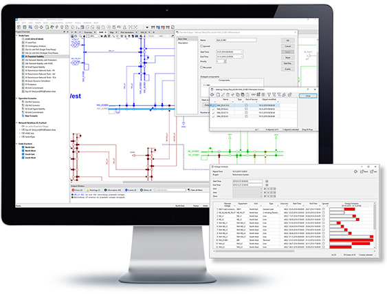
The Outage Planning tool enables the modelling of planned equipment outages, including the incorporation of associated system actions such as substation reconfiguration or load management. Outages are easily applied and reset, with a number of options available for visualising applied outages on graphics or viewing the outage plan for a period of time in tabular format.

- Tool for management of planned outages
- Schedule supports various recurrence patterns
- Support of associated remedial actions
- Action macro recorder to facilitate definition of remedial action events
- Integrated functions for apply and reset planned outages
- Tabular reports and Gantt diagrams with various filter options
- Graphical visualisation of outage and remedial actions, including affected regions
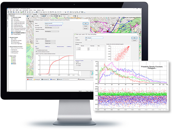
The Probabilistic Analysis allows network assessment based on probabilistic input data rather than assessment of individual operation scenarios or time sweeps. It becomes important as soon as input parameters are known to be random or if one wants to simulate the grid at some time in the future with forecast errors. A probabilistic assessment processes probabilistic data input and produces stochastic results.
Probabilistic Analysis is offered for:
- Load Flow Analysis;
- Optimal Power Flow.
- Network assessment based on probabilistic input data
- Supports Probabilistic Load Flow and Probabilistic Assessment of OPF*
- Unlimited stochastic input data modelling with flexible distribution curve objects
- Includes probabilistic modelling of generation with PV systems and/or wind generators, as well as variable load consumption
- Support of numerous distributions, such as uniform, normal, log-normal, Weibull, exponential, geometric, Bernoulli, finite discrete
- Modelling of dependencies via correlation objects
- Auto-conversion tool to estimate distributions and correlations based on historic profiles/time series data
- Monte Carlo and fast Quasi-Monte Carlo method
- Determination of statistical results for any calculation quantity, including means and standard deviations (with their confidence intervals), maxima, minima, higher order momenta
- Rich post-processing and plotting facilities for calculation results, including their distribution functions, density functions, correlations
- Post-assessment of critical worst-case or average cases via Probabilistic Analyzer
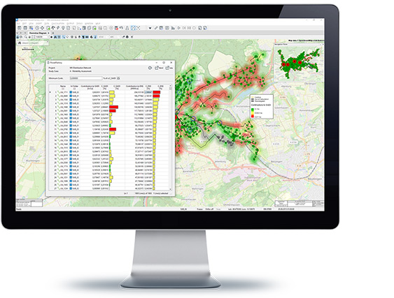
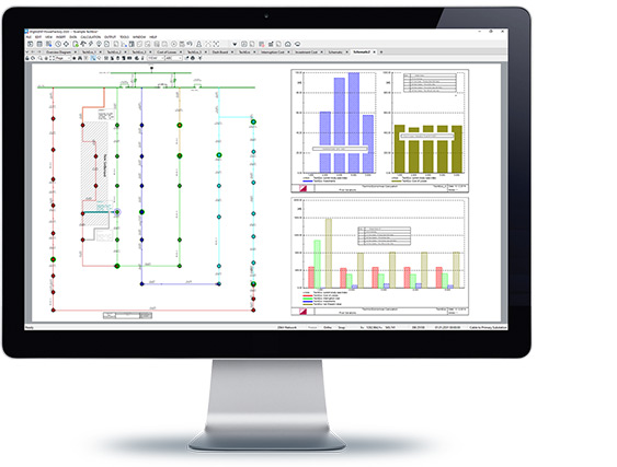
Network reliability assessment is used to calculate expected interruption frequencies and annual interruption costs. Reliability analysis is an automation and probabilistic extension of contingency evaluation. The relevance of each outage is considered using statistical data about the expected frequency and duration of outages, taking into account the protection systems and the network operator’s actions to re-supply interrupted customers. This optimal power restoration process can also be analysed and carried out for individual contingencies.
Reliability assessment involves determining, generally using statistical methods, the total electric interruptions for loads within a power system during an operating period. The interruptions and their effects are described by several indices, which are calculated in the simulation. Together with the reliability analysis, an optimal way of placing remote controlled switches (RCS) can be determined, in order to resupply as much demand as possible in the shortest time, with a given number of RCS. The package also includes Generation Adequacy Analysis, where the system supply capabilities are analysed with the help of stochastic methods.
Failure models
- Line, transformer, distribution transformer and busbar failures
- Generator failures with stochastic multi-state model
- n-1, n-2 and common mode failures (n-k)
- Double earth faults
- Independent second failures
- Protection/circuit breaker failures
- Protection over-function
Optimal Power Restoration
- Failure effect analysis (FEA)
- Automatic protection-based fault clearing
- Intelligent high-end system restoration with potential network ¬reconfiguration and load-shedding
- Support of branch and boundary flow limits, absolute ¬voltage and voltage drop/rise constraints
- Sectionalising (remote controlled switches, short-circuit ¬indicators, manual restoration)
- Substation automation with switching rules
- Animated tracing of individual cases
- Detailed reports for restoration action plans
Reliability Assessment
- Fast state enumeration incl. optimal power restoration techniques for balanced/unbalanced systems
- Calculation of all common reliability indices (IEEE 1366)
- Contribution of components to reliability indices
- Support of load variation, incl. load distribution curves
- Support of generation dispatch profiles
- Consideration of maintenance schedules
- Support of various tariff and cost models
- Support of parallelised Reliablity Assessment for multiprocessor hardware
Optimal Remote Control Switch (RCS) Placement
- Determination of optimal number and locations for RCS installation for improvement of system reliability
- Economic assessment for various objective functions
Optimal Manual Restoration
- Calculation of optimal switching scheme for manual power restoration phase
Generation Adequacy Analysis
- Stochastic assessment of system supply capabilities (loss of load probabilities, capacity credit, etc.)
- Consideration of generator outages and maintenance schedules (Monte Carlo), as well as load variation
- Enhanced probabilistic models for wind generation
- Rich suite of reporting and plotting tools
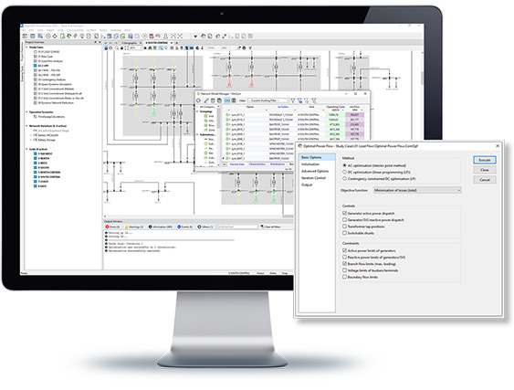
The PowerFactory Optimal Power Flow serves adds intelligence to the existing load flow functions. Where the standard load flow calculates branch flows and busbar voltages based on specified “set points” (active/reactive power generation, generator voltage, transformer tap positions, etc.), the OPF then calculates the “best possible” values for optimising a user-specified objective function and a number of user-defined constraints.
Reactive Power Optimisation (OPF I)
- Minimisation of total or partial grid losses
- Maximisation of reactive power reserve
- Reactive Power Optimisation (interior point method)
- Various controls such as:
- Generator reactive power
- Transformer and shunt taps
- Static Var Systems
- Flexible constraints such as:
- Branch flow and voltage limits
- Generator reactive power limits
- Reactive power reserve
- Boundary flows
- Various objective functions, e.g.:
- Minimisation of losses
- Minimisation of costs (eco dispatch)
- Minimisation of load shedding
- Optimisation of remedial post fault actions, e.g. booster tap changes (pre- to post fault)
- AC optimisation (interior point method)
- DC optimisation (linear programming)
- Various controls such as:
- Generator active and reactive power
- Transformer, quad booster and shunt taps
- Static Var Systems
- Flexible constraints such as:
- Branch flow and voltage limits
- Generator active and reactive power limits
- Active and reactive power reserve
- Boundary flows
- Contingency constraints (DC only)
Economic Dispatch (OPF II)
The Unit Commitment and Dispatch Optimisation tool allows users to easily complement traditional network simulation with a market simulation, without any need for an external tool, providing a single entry point of information for simulation models. The module solves the unit commitment linear-programming problem over a predefined period of time, while optimising the operating point of the dispatched generators such to minimise overall operating costs. Hence it smoothly combines the functionalities of a Quasi-Dynamic Simulation, Optimal Power Flow and Contingency Analysis. The function supports both internal as well as external LP-solvers like IBM CPLEX and GUROBI, thereby allowing the integration of existing LP simulation environments into PowerFactory.
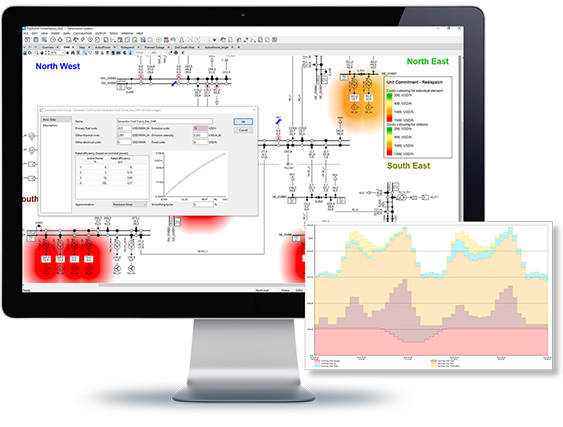
- Power plant dispatch optimisation for Market Simulation
- Minimisation of redispatch costs, such as operating, emission & startup costs, including curtailment of renewables/load shedding
- Optimisation (AC and/or DC) of generator dispatch schemes including hydro unit, batteries and general storage devices, as well as control units such as phase shifters and HVDCs
- State-of-the-art solutions for performance and memory efficiency
- User-definable time periods and resolutions
- Constraints including branch & boundary flow limits, voltages, as well as ramping, minimum up/down times or spinning reserves of generators
- Support of Contingency Constraint optimisation
- Seamless integration of all market parameters into network model
- Numerous reporting facilities, and result visualisations, including energy plots and dispatch schedules
- Post-assessment tools for detailed investigations
- Automated generation of optimal solution scenarios
- For standard size optimisation problems: ships with built-in solver
- For solving large-scale problems: integrated optional interface* to external solvers such as CPLEX, GUROBI or data exchange via AMPL-NL file format
Techno-Economical Calculation (TechEco) can be used to analyse costs and benefits of network expansion using the Net Present Value. TechEco analyses investment costs, cost of losses, interruption costs and the economic impact of project schedules.
- Economic assessment of network expansion strategies
- Net Present Value method considering costs of losses, investment costs, economic impact of failure rates (only with Reliability Analysis functions), and project schedules
- Efficiency ratio evaluation to determine optimal year of investment
- Support of parallelised execution of cases
- Reporting options for input data and calculation results
The State Estimation (SE) function of PowerFactory provides consistent load flow results for an entire power system, based on real time measurements, manually entered data and the network model. It provides bad data identification, observability analysis and state estimation.
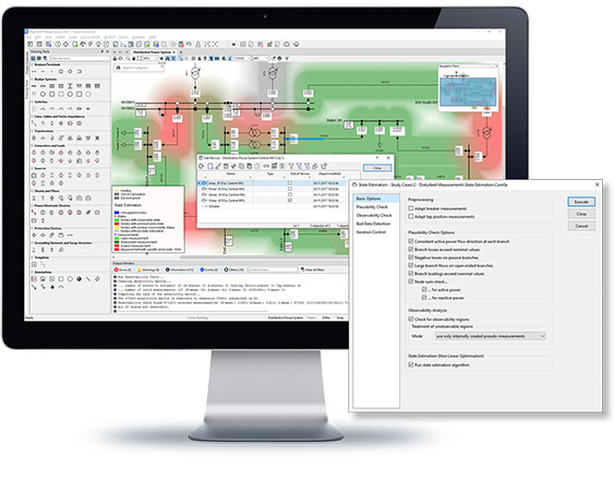
- P, Q, I and V-measurement models
- Measurement plausibility checks
- Automatic bad data detection/elimination
- Verification of system observability
- Various options to handle unobservable regions (e.g. pseudo measurements)
- Consideration of load flow constraints
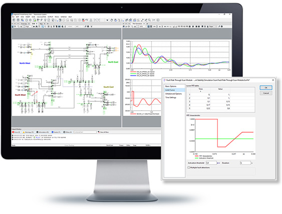
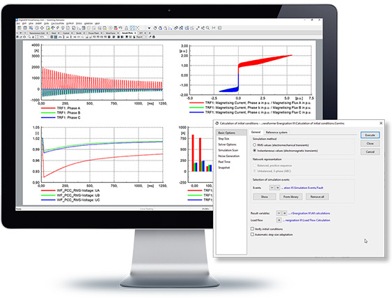
The RMS simulation tool in PowerFactory can be used to analyse mid-term and long-term transients under both balanced and unbalanced conditions, incorporating a simulation scan feature. DIgSILENT Simulation Language (DSL) is used for model definition, and a large library of IEEE standard models is available. Flexible co-simulation options are also available.
- Multi-phase AC networks, DC networks
- Support of balanced and unbalanced grid conditions
- Fast, fixed step size and adaptive step size algorithm
- A-stable numerical integration algorithms supporting long-term stability simulations with integration step sizes ranging from milliseconds to minutes, individually selectable for each model
- High precision event and interrupt handling
- Simulation of any kind of fault or event
- Transient motor starting (synchr./asynchr. machines)
- Support of all protection library relays
- Real-time simulation mode
- Simulation scan feature, e.g. frequency scan, loss of synchronism scan, synchronous machine speed scan, voltage-/voltage recovery scan, fault ride through scan or common variable scan
- Frequency Analysis Tool, including Fast Fourier Transform (FFT) and Prony Analysis for single point in time as well as time-range assessment
- Frequency Response Analysis tool for dynamic models with Bode/Nyquist plots
- Combined RMS and EMT simulation mode (requires Electromagnetic Transients functions (EMT))
DIgSILENT Simulation Language (DSL) for Dynamic RMS Modelling
- Graphical editor for drawing any kind of block diagram (AVR, prime mover, relay, etc.)
- Fully flexible signal wiring schemes having access to any grid object and their parameters via definition of Frames
- Nesting of frames and model building blocks
- Fully flexible definition of simulation functions via the DSL syntax
- High precision built-in macros & functions
- Automatic initialisation of complex, non-linear models
- Configuration scripts for initialisation using DPL
- Large built-in standard model library, including IEEE and CIM ENTSO-E models
- Generic C interface for user-defined controller models
- IEC61400-27-1 interface for external models
- Automatic DSL-to-C interface converter
- Support of model pre-compilation for improved performance
- Support of MATLAB/Simulink interface
- OPC interface* for real-time applications
- IEEE C37.118 simulation interface for PMU data streaming
- DSL Encryption function**
Co-Simulation Functionality
- Single domain co-simulation (RMS balanced – RMS balanced, RMS unbalanced – RMS unbalanced)
- Multiple domain co-simulation (RMS balanced – RMS unbalanced – EMT***)
- Co-simulation with external solver**** (e.g. third party power systems ¬simulation program) via IEEE C37.118 communication interface
- Computing supported as built-in for increased performance
- Both accurate (implicit) and fast (explicit) co-simulation methods available
- Easy to define co-simulation border using boundary objects
- Any number of co-simulation regions can be defined
- Co-simulation of networks split by regions depending on any criteria: localisation, voltage levels, etc.
*This function has to be requested separately.
**Licence for DPL/DSL/QDSL encryption required.
***EMT licence required.
****Requires separate „Co-Simulation Interface“ licence.
PowerFactory provides an EMT simulation kernel for solving power system transient problems such as lightning, switching and temporary over-voltages, inrush currents, ferro-resonance effects or sub-synchronous resonance problems. Together with a comprehensive model library, a graphical, user-definable modelling system (DSL), and options for co-simulation, it provides an extremely flexible and powerful platform for solving power system electromagnetic transient problems.
- Integrated simulation of electromagnetic transients in multiphase AC and DC systems
- Fast, fixed step size or adaptive step size algorithm
- Simulation of static var compensations (SVC), thyristor controlled series compensations (TCSC), FACTS, STATCOM, etc.
- Modelling of HVDC interconnections (rectifier/inverter, two-level VSC, half- and full-bridge MMC converter)
- Power electronic devices and discrete components (diode, thyristor, PWM converter, rectifier/inverter, DC valve, soft starter, etc.)
- Support of advanced constant and frequency-dependent distributed parameter models for OHL and cables
- Non-linear elements and saturation characteristics
- Series capacitors incl. spark gap model
- Surge arrestor models
- Impulse voltage & current source for lightning surge analysis
- Support of AC-DC intercircuit fault events
- Accurate EMT models of renewable generation (wind/PV, etc.) and storage systems
- Discrete R-L-C elements
- Flexible template definition to create and re-utilise user- specific models library
- Insulation coordination analysis including temporary (TOV), switching (SOV) and lightning (LOV) transient over-voltages
- Stochastic switching analysis and point-on-wave (POW) switching
- Frequency Analysis Tool, including Fast Fourier Transform (FFT) and Prony Analysis for single point in time as well as time-range assessment
- Inrush, ferro-resonance, SSR and TRV studies
- COMTRADE file support
- Sophisticated circuit breaker modelling and switch event options
DIgSILENT Simulation Language (DSL) for EMT Modelling
- Contains the DIgSLENT Simulation Language for dynamic modelling (see RMS module for details)
Co-Simulation Functionality
- Contains Co-Simulation functionality (see RMS module for details)
- Single and multiple domain co-simulation (RMS balanced , RMS unbalanced – EMT*)
*Requires Stability Analysis functions (RMS) licence.
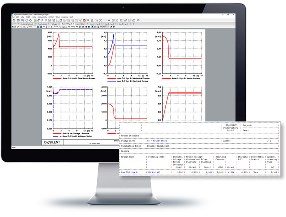
The Motor Starting Toolbox enables quick assessment of various motor starting scenarios and their impact on the system and reports commonly needed performance indicators like voltage drop before/during/after starting, starting time, grid loading, etc. The analysis is carried out via either a static calculation or a dynamic simulation. The toolbox features an easy to use analysis procedure that increases productivity while still retaining model customisation flexibility.
- Single or multiple motor starting
- Transient motor starting (synchr./asynchr. motors), with full support of controller models
- Steady-state motor starting
- Various motor starting methods (reactor, auto-transformer, variable rotor resistance, star delta, etc.)
- Thermal limit check of cables and transformers
- Automatic starting check function, visualised in Single Line Diagram
- Detailed report
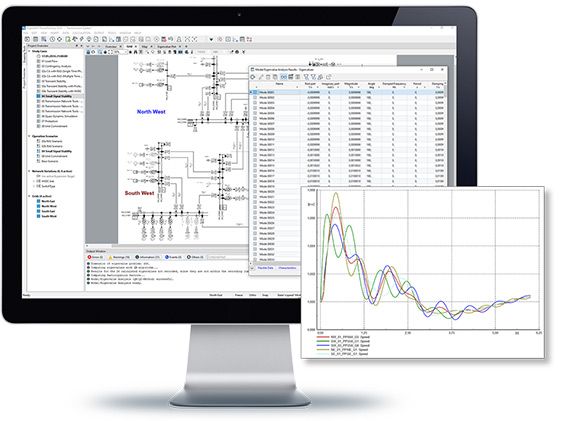
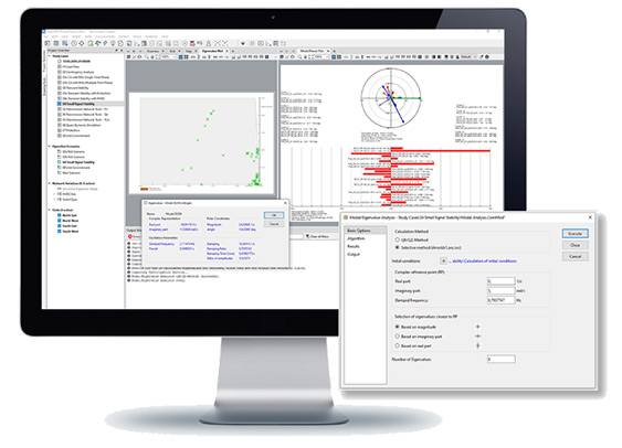
DIgSILENT PowerFactory offers a module for the analysis of the small signal stability in a power network, using an eigenvalue analysis tool which is suitable for balanced network representation. The calculation can be configured to consider all modes of oscillation in the system, or to perform a selective analysis (especially useful in large networks). It considers not only conventional generation, but also non-conventional generation such as wind turbines, PV systems and HVDC. The results can be visualised in an eigenvalue plot or tabular reports, including all relevant information such as frequency of oscillation, damping and damping ratio. In addition, the participation factors of the state variables, observability (right eigenvectors) and controllability (left eigenvectors) can be visualised in bar and phasor plots.
- Full and selective eigenvalue analysis
- Balanced (positive sequence) network representation, including combined AC and DC modelling, with non-conventional generation such as wind turbines, PV systems, HVDC, VSC and other FACTS devices
- Interactive eigenvalue, mode bar and mode phasor plots
- Visualisation of eigenvectors in network diagrams
- Tabular reports of eigenvalues incl. damped frequencies, damping time constants, etc.
- Detailed reports of oscillatory modes including participation factors of state variables, controllability and observability
This built-in system of identification and general optimisation procedures provide an easy and accurate method to perform model parameter identification on the basis of system tests and field measurements, working from input reference values generated in PowerFactory or taken from external files. Suitable for load flow models as well as time-domain simulation models, it is able to identify multiple parameters at once, with constrained (only positive) and unconstrained options available for each parameter and is fully integrated into the graphical frame definition and block diagrams. The optimisation procedures provided are highly generic and can also be used for optimally tuning parameters such as PSS settings according to defined model response functions.
- Parameter estimation of non-linear dynamic MIMO-systems fully integrated with DSL modelling
- Black box parameter estimation of non-linear systems
- Identification of any calculation relevant parameter (type, element, control model)
- Multi-parameter identification with flexible upper-/lower- limitation
- Various algorithms available (gradient based, swarm intelligence, pattern search, global optimisers)
- Support of load flow, RMS-simulation (balanced/unbalanced) and EMT-simulation
- Multiple options for optimisation, using field measurement data or simulation results
- API - Application Interface (API is part of the module “Scripting and Automation”, see following section)
- OPC DA/UA Interface1 - SCADA interoperability standard, A/D signal interfacing
- Unit Commitment Interface (for external solvers CPLEX, ¬GUROBI or data exchange via AMPL-NL file format)
- IEEE C37.118 simulation interface1 – PMU protocol
- Co-Simulation interface: C37 protocol based third party EMT/RMS co-¬simulation interface
Automation of PowerFactory tasks is possible using Python or the DIgSILENT Programming Language (DPL), and is further enhanced with Add-on Modules to allow users to extend the existing PowerFactory Functionality.
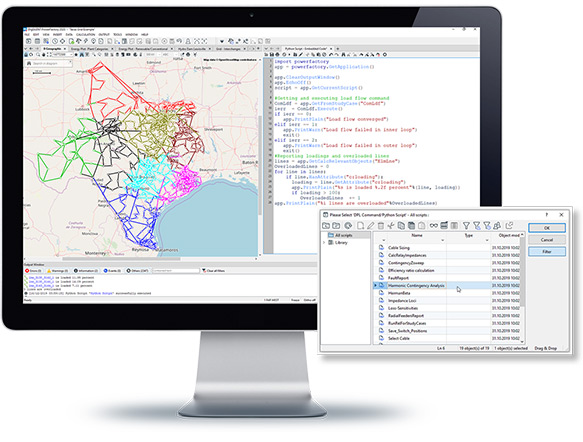
- Python: Integration of Python as programming language with full PowerFactory data model access and rich function suite
- DPL (DIgSILENT Programming Language):
- C-like syntax supporting unlimited access to PowerFactory objects, parameters and their functionality
- Extendable function scope of DPL via C-Interface, thus allowing access to external data and applications
- Encryption of DPL Scripts*
- Detailed Scripting Reference documentation for Python/DPL (750+ pages) including function descriptions and example code snippets
- Add-on Modules: framework for user-extendable function scope including data model extension concept for user-definable input attributes and result parameters
- API (Application Interface): C++ interface for full external automation of PowerFactory
- Task Automation Tool for parallelised execution of calculation functions and scripts